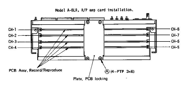
6.4.1 Calibrating the Dolby encode mode and meters.
1) Put transport in the EDIT mode. To calibrate TRACK 1, depress the RECORD
TRACK 1 button, simultaneously depress RECORD and PLAY buttons to put TRACK 1
(CHAN. 1) in the record mode.
2) Plug in an audio oscillator output to the recorder rear panel INPUT 1 jack
and apply a 400Hz, -10dBV (0.3V) signal.
3) Set the NR INT/EXT switch on the recorder front panel to EXT,
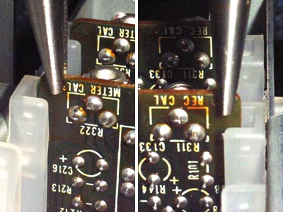
connect a level meter to test point TP-101 and adjust REC CAL (R-311, 10KΩB) so that the level here is 390mV.
4) On completing the above adjustments, connect the level meter to OUTPUT 1 jack
on the recorder rear panel and check that the level here is -10dBV (0.3V) ±1dB.
5) After checking the OUTPUT jack level, adjust METER CAL (R-312, 50KΩB) for a
0 VU reading on the recorder VU meter.
6) Calibrate tracks 2 ~ 8 in the same way.
7) Return the NR INT/EXT switch, on the recorder front panel, to INT.
6.4.1 Dolby録音に必要な基礎調整とVUメーターの調整
1.フロント・パネルの「 EDIT mode 」をオンにする。
TRACK 1を調整する為、TRACK 1のレコード・ファンクションをオンし、RECORDとPLAYボタンを同時に押す。
2.背面のINPUT-1に、オシレーターの400Hz ( -10dBV = 0.3V )信号を入力する。
3.フロント・パネルの「 NR 」スイッチを「EXT」側にし、基盤の「TP-101」出力にテスターをつないで、
ここの出力が 390mV になる様に、REC CAL (R-311)で調整する。
4.調整が済んだら、OUTPUT 1 jack にテスターをつなぎ、 -10dBV (0.3V) ±1dB になっているかをチェックする。
5.OUTPUT jack level のチェック終了後、METER CAL (R-312)を使って、レコーダーのメーターが0 VU になる様に調整する。
6.同じ様に、2〜8トラックを調整する。
7.すべての調整後、 NR INT/EXT switch を「 INT 」に戻す。
6.4.2 Carlibrating the Dolby decode mode
1) Set the NR INT/EXT switch on the recorder front panel to EXT and switch off
all RECORD TRACK buttons.
2) Playback the Reference Level Section of the Reproduce Alignment Tape.
3) Beginning adjustment from TRACK 1 (CHAN 1), connect a level meter to test
point TP-101 located near U106 upon the CHAN 1 PCB of the record/reproduce
amplifier, and adjust REP CAL (R314,10KΩB) so that the level is 390mV.
4) After these adjustments, connect the level meter to the recorder rear panel
OUTPUT 1 jack and check that the level is -10dBV (0.3V) ±1dB.
5) After check of the OUTPUT jack level, confirm that the meter reading is
0 VU, ±1 VU.
If the reading is not 0 VU ±1 VU, repeat the adjustments in the previous
section, Item 5.
6) Calibrate tracks 2 ~ 8 (CHAN 2 ~ 8) by the same procedures for TRACK 1, above.
7) On completing the above adjustments, return to INT the NR INT/EXT switch on
the recorder front panel.
6.4.2 Dolby再生に必要な基礎調整
1) レコーダー・フロントパネルの"NR INT/EXTスイッチ"をEXT、さらに、
すべてのRECORD TRACKのファンクション・スイッチを切ってください。
2) アライメント・テープ(テスト・テープ)を再生します。
3) TRACK 1(CHAN 1)からの調整を開始します、
record/reproduce amplifier のCHAN 1 PCB基盤の上の、U106の近くに位置する「TP-101」にテスターを当てます。
ここのレベルが390mVになる様に、REP CAL(R314,10KΩB)を調節してください。
4) これらの調整の後、レコーダー後部のOUTPUT 1ジャックにテスターを当て、
レベルが-10dBV(0.3V)±1dBであることを確認してください。
5) OUTPUTジャック・レベルのチェックの後、本体のメーターが、0VU ±1VU であることを確認してください。
もし0VU ±1VU でないならば、前のセクション(6.4.1 の第5項)の調整を繰り返します。
6) TRACK 1(上の)の同じ手続きによって、トラック2〜8(CHAN 2 〜 8)を調整してください。
7) 上記の調整を完了したら、レコーダー・フロントパネルの"NR INT/EXTスイッチ"を INT に戻してください。
6.4.6 Bias current adjustment
The track of which bias current is to be adjusted is put in the record mode.
To adjust TRACK 1, for example, hook the oscilloscope probe hot side to TP-102
located near connector J-101, and the ground clip to the GND pin.
Then, set the BIAS LVL pot, R317, 47KΩB at approximately 450mV P-P.
For an accurate adjustment, load a blank tape (Ampex "457, Scotch "277) on the recorder,
record a test signal, set the NR switch to INT, and trim the BIAS LVL pot
so that the overall frequency response is within 3dB between 250Hz and 10KHz, or
within 5dB when the higher end is 14KHz.
During this adjustment, temporarily set the screwdriver adjusting slot of REC EQ,
R316, 1KΩB so that this slot is parallel with the PCB plane, then trim it
for a more flat overall frequency response.
6.4.6バイアス電流調整
バイアス調整するために、記録モードにします。
TRACK 1を調節するにあたり、たとえば、オシロスコープの「hot側」を「J-101」コネクター近辺にある「TP-102」、
「ground clip」をGNDピンへ。
それから、BIAS LVL ポット(R317、47KΩB)で、450mVのP-Pでセットしてください。
*この作業は製作工場、またはメーカーメンテナンスが保有の延長基板を使わないと調整できません。
通常メンテナンス調整の場合、このステップを飛ばしても、さして問題はありません。
正確な調整のために、レコーダーに空のテープ(アンペックス#457、スコッチ#277)をかけ、
NRスイッチをINTにした状態でテスト信号を録音します。
全体的な平均周波数レスポンスが250Hz〜10KHzの間で3dB以内に、
より高い周波数の14KHz以上の場合、5dB以内になるように、BIAS LVL potで微調整します。
この調整と平行し、より平均的な周波数レスポンスに追い込む為、一時的に REC EQ (R316、1KΩB)で微調整します。
6.4.7 Recording level adjustment
1) Proceed to the following adjustments only after checks and adjustments in the
previous Sections 6.4.1 ~ 6.4.6 have been completed.
set the front panel NR INT/EXT switch to EXT.
2) Load a blank tape (Ampex 457 or Scotch 277) on the transport and apply an audio
oscillator output of 400Hz, -10dBV (0.3V) to the INPUT jack on the recorder rear panel.
Also, plug in a level meter to the OUTPUT jack.
Taking TRACK 1 as an example, the connector number is "1" for both INPUT and OUTPUT jacks.
3) Depress the RECORD TRACK 1 button, then, depress the RECORD and PLAY buttons to
put TRACK 1 in the record mode.
When thus in the record mode, the meter will indicate the input level regardless
to select position of the input button.
Check to see that the reading of this meter is 0 VU ±1 VU.
4) It will be convenient to rewind the tape to the start if the tape index counter
reset button is depressed, at start of recording, to return the display to 0000.
5) After recording a certain length of 400Hz, 0 VU signal, depress the ZERO RTN
button to rewind tape to the starting point, put the transport in the PLAY mode
and check the meter reading. The MONITOR switch must be at TAPE.
It is in normal condition if the meter reading is 0 VU ±1.5 VU.
If it is off spec, correct by adjusting REC LVL R315, 5KΩB.
Do the same on the remaining track 2 ~ 8.
6.4.7レコーディング・レベルの調整
1) 前のセクション6.4.1 ~ 6.4.6における停止と調整が完了したあとだけ、以下の調整まで進行してください。
フロントパネルNR INT/EXTスイッチをEXTに設定してください。
2) 乗物に空白のテープ(アンペックス457またはスコッチ277)を積んで、
400Hz(レコーダー後部制御盤のINPUTジャッキへの-10dBV(0.3V))の音声発振器出力を適用してください。
また、OUTPUTジャッキにレベル・メートルのプラグを差し込んでください。
例証としてTRACK 1をして、コネクタ番号は、INPUTとOUTPUTジャッキのための「1」です。
3) TRACK 1がボタンを掛けるRECORDを落ち込ませてください、
そして、TRACK 1を記録モードに入れるために、RECORDとPLAYボタンを押してください。
記録モードでこのようにあるとき、メーターは気にせずに入力ボタンの選ばれた位置に入力レベルを示します。
このメーターの表示が0のVU±1 VUであるのを見るために、チェックしてください。
4) テープ・インデックス・カウンター・リセット・ボタンが落ち込むならば、始まりにテープを巻き戻すことは便利です、
0000に表示を返すために、レコーディングのスタートで。
5) 400Hzの特定の長さを記録した後に、0のVUは、合図して、出発点にテープを巻き戻すためにZERO RTNボタンを押して、
輸送をPLAYモードに入れて、読んでいるメーターをチェックします。MONITORスイッチは、TAPEでなければなりません。
メーター記録が0のVU±1.5 VUであるならば、それは通常の状態にあります。
それがスペックをやめていて、REC LVL R315を調節することによって正しいならば、
5KΩB.は残りのトラック2 ~ 8の上で同じようにします。
6.4.8 Overall frequency response
1) With the front panel NR INT/EXT switch at EXT and under the measurement setup
of the previous Section 6.4.7, apply signals from 40Hz through 18KHz (15 ips)
and 40Hz through 15KHz (7-1/2 ips) at -10dBV (0.3V) to the recorder INPUT jack
and set the NR switch to INT.
To adjust TRACK 1, for example, apply the signal to INPUT 1 and plug in a level
meter to OUTPUT jack 1. Put TRACK 1 in the record mode to record a certain length
of the signal, rewind it to the start, and playback the tape. It is in good
nomal condition if the frequency response in reference to 400Hz is within +3dB and -3dB.
If it does not fall within spec in the high frequency region, correct it by a
slight rotation of REC EQ pot R316, 1KΩB.
2) Check and adjust the remaining tracks in the same way.
6.4.8全体的な周波数レスポンス
1) フロントパネルNRで、INT/EXTはEXTで、そして、前の第6.4.7節の測定セットアップ中で変わって、
レコーダーINPUTジャッキに-10dBV(0.3V)で15KHz(7-1/2ips)を通して
40Hzから18KHz(15ips)と40Hzまで信号を適用して、NRスイッチをINTに設定します。
調整されるために、TRACK 1は、たとえば、信号をINPUT 1に適用して、OUTPUTジャッキ1にレベル・メートルのプラグを差し込みます。
信号の特定の長さを記録する記録モードの置かれたTRACK 1は始まりにそれを巻き戻します、
そして、再生がテープです。
400Hzに関する周波数レスポンスが+3dBと-3dB以内にあるならば、それは良いnomalな状態にあります。
それが高周波地域で思惑に入らないならば、REC EQポットR316(1KΩB)のわずかな回転によってそれを修正してください。
2) 同様に残りのトラックをチェックして、調節してください。
|
|
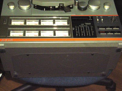
R/P AMP 基盤の取り外し方
|
|
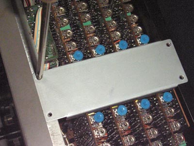
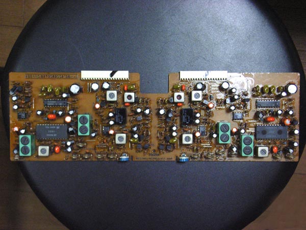
分かり易い様、2枚ほど基盤を抜いた状態を載せています。
オーディオ基盤は写真下(フロント側)から、
8&1、7&2、6&3、5&4
というチャンネルペアで、1枚基盤(計4枚)になっている。
写真中央を見て頂ければわかる様に、
ここの基盤はコネクター差込みのみとなっている。
基盤のチャンネル割りは、フロント面からそれぞれ、
VUメーター側が1〜4、
走行ボタン側が8〜5となっている。
|
|
基盤の抜き方であるが、
メーカー修理の場合は専用工具があったと思われるが、
今回はニッパーを使っての作業となる。
写真の様に、基盤の最端の部分をつまんで、少々引っ張っては、
基盤の反対端の部分を同じ様に少々引っ張り、
徐々に丁寧に抜いていく。
オーディオの特定チャンネルに入力信号が行かなくなった…等の場合、
コネクター部分の接触不良で、一度だけ抜き差しするだけでも
簡単に改善できてしまうケースもある。
(ボリューム等の"ガリ"みたいなもの)
こういう場合、安易に「接点復活剤」は使わない方が良いと思う。
|
|
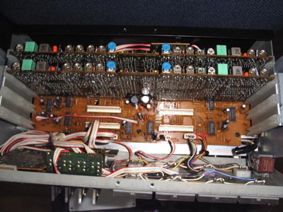
引き抜いたオーディオ基盤の全景。
|
|
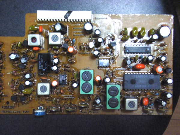
コネクター「J101」側の基盤(上写真の右側ブロック)
基盤に乗っているIC は、ドルビー・マーク付で、
大型IC → TEA 0654
小型IC → TEA 0652
という型番印刷がされている。
|
|
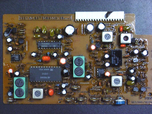
コネクター「J201」側の基盤(上写真の左側ブロック)
FOSTEX社の「A8LR-AMPLIFIER」回路図を参照してみると…。
入力系で音の不具合が出ていた場合、まず、
基板上の「C101」コンデンサーを交換してみる。
再生系の不具合であれば、「C112」「C114」、
ドルビー絡みであれば、下記に挙げてみたコンデンサーを
交換してみるのも良いかもしれない。
C101 = 1/50V
C112 = 33/16V
C114 = 10/16V
C103 = 10/16V
C104 = 0.047
C105 = 10/16V
C106 = 0.22/50V
C107 = 470/10V
|
|
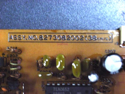
基盤を見てみると、「38cm/s」という表示がある。
A8LR は当時、テープスピード"19cm/s" と "38cm/s" の2タイプが販売されていた。
オーディオ基盤でも、ボリューム調整以外に、何か設計が違うらしい。
|
オーディオ基盤は直接、音に関わる箇所でもあり、もろもろ触る事はお奨めできない。
できれば、専門オープンリール業者に頼んで調整して頂いた方が、末永く愛用できるかと思う。
|