 Å@
Å@ Å@
Å@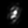
Adaptive Optics
This page is displayed with Internet Explore only.
Here, I explain the adaptive optics which reduce or remove seeing caused by the atmosphere. My simulation shows you how it is going on and how it reduce
the seeing. At first, let's see a simulation of seeing.
Å@Å@
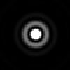
Simulation images
Left : in vacuum , Mid : on the ground , Right : an integral image on the ground
Aperture 200mm , Fno=10.0 , at 500 nm wavelength
50 microns square ( app. 5.0 arc seconds )
ReferenceÅ@ÅFÅ@Actual Seeing
The left is a simulation image, which means the perfect star image in vacuum. The middle is an animation on the ground, so it is turbulent by an atmosphere.
The air does not have the constant index because somewhere is warm and the other is cold. Those different temperature makes light path bend. This causes
seeing images, turbulent images. If we know the turbulent light path, we can fix it and get the perfect images. This is the adaptive optics.
Adaptive optics has two large parts in general. First one is the wave front sensor, which measures how the light path is bending. The other one is the adaptive
part, which corrects the bending light with maneuver of mirrors.
This page explains the wave front sensor, and it corrects the turbulent images in simulation. It is not difficult to simulate that, but is very hard to make the
adaptive optics for amateurs actually.
Remember "wave front" which is a plane that is perpendicular with light ray. This concept is very useful to think about the adaptive optics.
Let's see the relationship between incident angles and positions of stars on CCD.
incident angles and positions of stars
As you see it, the straight light from the star goes through the lens and arrives at the center of the CCD. The light coming from right reaches at the left side of
the CCD. Like this, the light coming from left is on the right side of the CCD. We understand the relationship between the incident angles and positions of
stars on CCD easily. The red lines are the wave front, which is always vertical with light path.
Adding up to 5 lenses, see more.
Turbulent wave front is coming into the lenses.
This wave front is turbulent, but each part of wave is an inclined straight wave for each lens. Therefore, each part of wave front goes through the lens and
makes an image on the CCD. Each position means how the incident wave front is inclined, according to how far the position is.
Let's see the layout including telescope's focus point.
Layout
F1 is the telescope focus point, CL1 is a collimate lens, and L1 is a lens array.
Recall the calculus. An inclined of a part of a function is differential, and we can get the whole function after integral of it. Therefore, an integral of ray of each
position makes the whole wave front.
To be continued
The results of simulations is coming soon.